Large castings reliably desanded using blasting technology
Published: | clamping, measuring, manufacturing, Stolle, shot blasting, workpieces

Well-founded expertise from more than 120 years of company existence and state-of-the-art manufacturing solutions: This combination makes the Stolle company a trustworthy and reliable partner for its customers. Even the brand name "STOLLE castable solutions" expresses performance, product complexity and innovative strength. The company supplies clamping plates, measuring plates and special constructions worldwide, from planning, development, construction, model making and casting to the finished plate, including logistics to the place of use and assembly.
The clamping, measuring and testing plates can reach a unit weight of up to 25 t. This initially requires a very precise and sophisticated casting process. The following processing steps also have to meet requirements that are not commonplace.
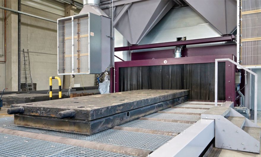
Recently, Stolle invested in a new shot blast plant from AGTOS. It is a roller conveyor shot blast plant of type RT 32-10. It can process workpieces with a width of up to 3,200 mm and a height of 1,000 mm.
The aim of the blasting process is to desand the raw castings. The parts had to pass through the previously used plant in an older building complex two to three times before the result passed the subsequent quality control. In addition, the parts had to be manually swept and cleaned of abrasive. The blasting process was therefore to be accelerated and automated. Both have been achieved. Florian Lorenz, Production Manager Foundry, says: "The special feature for us was that the plant has a very high degree of automation, that we actually only have to place a product and press the start button. Then the plant runs completely automatically and the product comes out clean at the back. It also switches itself off automatically. Another special feature is the space-saving concept. We actually only have the shot blast plant on the ground and above it is the complete cleaning station, the abrasive reclamation unit and the filter unit. It is very important for us that we can make good use of the hall space."
Special features of blasting technology
The process analysis showed that a roller conveyor shot blast plant, as with the previous plant, was the best option for the customer. The workpieces arrive in the hall built for finishing on plateau trolleys pulled by forklifts and are then placed on the infeed roller conveyor by crane.
The design of the blast machine differs fundamentally from the previous model. For example, the pedestal bearings of the rollers of the infeed roller table were insulated by 10 mm thick elastomers. In this way, shocks caused by the crane when loading the heavy workpieces are effectively cushioned. Wear on the pedestal bearings, rollers and steel structure caused by the placement of the workpieces is reduced. The roller conveyors in the infeed and outfeed areas as well as in the actual blasting chamber are each driven separately to enable the cycle of workpieces. The chain is driven from roller to roller by a geared motor. This is infinitely variable and reversible with the help of a frequency converter in a ratio of 1:5 from 0.4 - 2.0 m/min.
The feed rate is set on the control unit and displayed digitally in m/min.
In the direct blasting area, the rollers are made of highly wear-resistant material. All bearings are mounted on the outside and additionally protected against dust and abrasive by labyrinths.
The worker starts the roll feed at the push of a button and all subsequent process steps run automatically afterwards. He can therefore take on other tasks in the meantime. The workpieces arrive in front of the machine's inlet portal and are detected by a light barrier. Only shortly before the workpieces reach the blasting chamber with the high-performance turbines they start up and the entire machine is ramped up. This saves a lot of energy.
The side walls of the blasting chamber are fitted on the inside with wear-resistant, easily replaceable plates so that vagrant abrasif cannot damage them. The inlet sluice is equipped with wear-resistant rubber curtains for sealing. Sealing from below is achieved by rubber seals. In this way, no dust gets into the environment.
When the 12 high-performance turbines, which process the workpiece in the next 8-10 minutes, start up, the fan of the cartridge filter unit, which is located in the upper area of the machine to save space, starts. It ensures the dedusting of the machine by means of a vacuum.
The highly varied, complex surface of the different workpieces has one thing in common: the top side is smooth. Holes, pockets and other geometries are found on the underside of the workpieces. Therefore, 8 high-performance turbines were installed in the lower area of the blast machine and only four in the upper area.
The geometry of the workpieces means that there are large amounts of moulding sand in the abrasive during the blasting process. Therefore, a solution was created to allow parts of the abrasive to pass through the circuit several times during and after the blasting process so that it is optimally cleaned. This measure made it possible to dispense with a magnetic/wind sifting system, which is otherwise common in the foundry sector, and thus avoid investment costs.
The cleaning station that follows the blasting process receives the data from the height detection of the workpieces in order to position the brush appropriately for the surface. It is important that the bristles only touch the surfaces minimally. Otherwise they wear out too quickly. Additionally installed nozzles blow off the workpieces. Manual sweeping is not necessary. All the abrasive is collected in the bottom area of the blast machine, freed from coarse impurities by means of a vibro chute and passes into the upper part of the machine via a bucket elevator. Here, a well adjustable, optimally designed wind sifter ensures that sand, dust and undersize particles are removed from the abrasive. The cleaned abrasive is fed back to the turbines and the cycle is closed.
Another option allows the customer to make better use of the process heat. Thus, a summer/winter change-over flap was installed behind the AGTOS cartridge filter unit. In winter, the air that has been cleaned more than in accordance with regulations can be blown back into the hall from the cartridge filter unit. As a result, the hall air heats up. This reduces the heating costs.
Rapid and competent cooperation
Both in the project phase, as well as during the installation of the machine and the commissioning up to the production support, the exchange was right. Lorenz: "Due to intensive consultation during the project phase, we only had a few changes afterwards. We were able to solve small questions very well. We stayed completely on schedule. The cooperation was again very good. When we had adjustment work, we could quickly access the AGTOS mechanics. Within a few hours, it was possible for someone to be with us and help us adjust processes or optimise the blasting quality even further."
AGTOS GmbH Te: 0049-2572-96026-200 Email:
Quick Links
Telephone
Published By
Roger Barber Publishing
4 Mayfair Court
Cleethorpes
South Humberside
DN35 0QG
© Copyright Roger Barber Publishing , all rights reserved.
Terms and Conditions apply. This website uses cookies, click here for blocking details. Our Privacy Policy is available here.

